Aluminum CNC Turning Parts for 5-Axis Aerospace
Date:2026-07-16Article editor:Starting Point PrecisionViews:252In the demanding realm of aerospace manufacturing, the production of high‑precision Aluminum CNC Turning Parts represents a critical intersection of material science, mechanical engineering, and advanced machining strategy. As aircraft designs evolve toward greater efficiency and performance, the need for lightweight, complex geometries has never been more acute. This exploration delves into the sophisticated processes behind manufacturing these essential components, focusing on the challenges and solutions in 5‑axis machining.
The aerospace industry’s relentless pursuit of weight reduction and structural integrity has made aluminum alloys, particularly 7075 and 6061(per ASTM B209), the materials of choice for countless airframe and engine components. However, machining these materials on 5‑axis CNC turning centers presents unique obstacles:
◆ Complex geometries – 5‑axis capability allows single‑setup production of contoured, non‑linear shapes, but this introduces intricate tool‑path generation and work‑holding demands.
◆ Thin‑wall susceptibility – Aerospace parts often feature thin ribs and walls that are prone to vibration, chatter, and deflection under cutting forces.
◆ Chip evacuation – Deep pockets and oblique features complicate chip removal, risking tool damage and surface quality.
Unlike conventional 3‑axis operations, 5‑axis machining offers substantial benefits—drastic reduction in production time and superior accuracy—yet these advantages can only be realized through meticulous process planning.
Achieving the delicate balance between micron‑level precision and high‑volume efficiency is the holy grail of aerospace machining. The economic pressures of the aerospace supply chain demand rapid cycle times and minimal material waste. This balancing act requires a holistic approach integrating:
◆ Multi‑tasking machines – Combining turning, milling, and drilling in one setup reduces handling errors and ensures geometric integrity of Aluminum CNC Turning Parts from raw stock to finished product.
◆ Optimized cutting parameters – Selecting appropriate speeds, feeds, and depths of cut to maximise metal removal while preserving tool life and part stability.
◆ Advanced CAM strategies – Employing adaptive roughing, trochoidal milling, and high‑feed techniques to maintain consistent chip loads and minimise force spikes.
Leveraging the advanced capabilities of a Germany DMG CTX beta 800 or the multi‑tasking prowess of a Japan TAKZSAWA NEX‑108 allows manufacturers to achieve this equilibrium, delivering parts that meet both stringent aerospace standards and cost targets.
The foundation of successful aerospace machining lies in the selection and utilisation of world‑class equipment. State‑of‑the‑art facilities, like those at Dongguan Start Point Precision Technology Co., Ltd., leverage a diverse fleet of machinery. For 5‑axis work, the Germany DMG HSC 75 linear (visit DMG MORI official site for technical specifications) is a powerhouse, offering exceptional dynamics and precision for complex curved surfaces and oblique features. Complementing this are robust Vertical Machining Centers such as the Japan LGMazak VCN‑510C and United States HAAS VF3, which are essential for secondary operations and prismatic features.
The synergy between these machines, managed by skilled programmers, is key to transforming raw aluminum bar stock into flight‑ready components. A typical process flow includes:
| Operation Stage | Equipment Example | Key Parameter |
| High‑speed roughing | DMG HSC 75 linear / HAAS VF3 | Depth of cut: 2–4 mm, Feed: 0.1–0.2 mm/rev |
| Semi‑finishing | LGMazak VCN‑510C | Radial engagement ≤ 30% of tool diameter |
| Precision finishing | DMG CTX beta 800 | Tolerance: ±0.005 mm, Surface roughness Ra ≤ 0.8 μm |
For a complete equipment list, including Germany DMG CTX beta 800, Japan TAKZSAWA NEX‑108, and other precision assets, refer to the Precision Equipment List available on our website.
Perhaps the most critical element in machining high‑quality Aluminum CNC Turning Parts for aerospace is tool path optimization, particularly when dealing with thin‑walled sections. Machining a thin‑walled aerospace component—such as a structural rib or a casing—is fraught with risk; cutting forces can easily cause the part to deflect or chatter, leading to out‑of‑tolerance conditions or scrapped parts. To mitigate this, advanced CAM strategies are employed:
◆ Trochoidal milling – Uses circular tool paths with a small radial depth of cut and a large axial depth, minimising radial engagement and significantly reducing cutting forces and heat generation.
◆ Adaptive roughing – Maintains a constant chip load, ensuring smoother cutting action and protecting both the tool and the thin‑walled workpiece.
◆ High‑feed milling – Employs specialised tooling to achieve very high metal removal rates at low cutting depths, which is invaluable for efficiently roughing out pockets while minimising stress on the part.
◆ Constant scallop‑height finishing – Ensures uniform surface finish and consistent step‑over for finishing ball‑nose end mills, reducing cycle time and improving quality.
Additionally, dynamic work‑holding solutions (e.g., custom vacuum fixtures that support thin walls from the backside) are often combined with these tool‑path strategies to prevent deflection during final passes.
Consider a real‑world example of an aerospace turbine assembly – a critical rotating component manufactured from 7075 aluminum. The assembly featured a complex, contoured main body with multiple thin‑walled flanges, deep internal cavities, and precision bore features that must maintain concentricity under extreme operational loads. Initial attempts using conventional 2D tool paths resulted in unacceptable chatter, poor surface finish on critical sealing surfaces, and a 15% rejection rate due to wall thickness variation and bore ovality.
By implementing a 5‑axis simultaneous machining strategy with optimised tool paths, the process was transformed:
| Action | Implementation | Result |
| High‑efficiency roughing | Trochoidal milling with a high‑feed end mill to rapidly remove bulk material while maintaining low radial forces, preserving the rigidity of the remaining thin walls. | Reduced roughing time by 25% |
| Adaptive finishing | Constant scallop‑height tool path with consistent step‑over for the finishing ball‑nose end mill, applied to both external contours and internal cavities. | Uniform surface finish (Ra 0.6 μm) on all aerodynamic surfaces |
| Precision boring | Custom‑ground PCD boring bars with vibration‑damping shanks, combined with a helical interpolation strategy to minimise cutting forces on the thin‑walled bore sections. | Bore concentricity within 0.01 mm, elimination of ovality |
| Dynamic work‑holding | Custom vacuum fixture with integrated support pins that back up the thin walls from the inside, preventing deflection during final finishing passes. | Dimensional scrap reduced to zero |
The outcome: Cycle time reduced by 20%, scrap rate dropped from 15% to 0%, and all critical dimensions – including wall thickness, bore roundness, and surface finish – were consistently maintained within aerospace tolerances. This case demonstrates that targeted optimisation—combining tool‑path intelligence, specialised tooling, and robust work‑holding—can simultaneously achieve precision and efficiency on complex aluminum turbine assemblies.
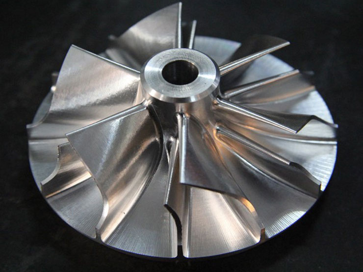
The successful production of Aluminum CNC Turning Parts for 5‑axis aerospace applications is a testament to the power of combining advanced manufacturing technology with sophisticated process knowledge. By mastering the challenges of thin‑wall stability, optimising tool paths to balance high metal removal rates with micron‑level accuracy, and leveraging the capabilities of world‑class equipment like the DMG and Mazak machining centers, manufacturers can consistently deliver the high‑quality components the aerospace industry demands.
Contact us to discuss your manufacturing needs and discover how our expertise in precision machining can support your next project.
1. What are the primary challenges when machining aluminum for aerospace components?
The main challenges include managing built‑up edge (BUE) on cutting tools, controlling chip evacuation to prevent re‑cutting, and mitigating vibrations and deflections, especially when machining thin‑walled, complex geometries common in aerospace designs.
2. How does 5‑axis machining improve the production of aluminum parts?
5‑axis machining allows a part to be machined in a single setup, which drastically improves accuracy by eliminating errors from multiple fixtures. It also enables the creation of complex, contoured surfaces that are impossible or very difficult to produce on 3‑axis machines.
3. What are the key strategies for tool path optimization to prevent chatter?
Key strategies include using trochoidal or high‑efficiency milling paths to control radial engagement, employing adaptive clearing strategies that maintain a constant chip load, and utilising high‑feed milling techniques for roughing to reduce cutting forces.
4. How do you ensure the dimensional stability of thin‑walled aluminum parts during machining?
Dimensional stability is ensured through a combination of strategies: using optimised tool paths that apply lower radial forces, implementing specialised work‑holding solutions like vacuum chucks or custom fixtures to support the part, and often employing techniques like high‑pressure coolant to manage thermal expansion.
Add: Building 3No.277 Zhen'an Middle Road, Chang'an Town,Dongguan,Guangdong, China
Tel:+86-769-82855591
Copyright © 2019 All Rights Reserved Dongguan Start Precision Technology Co., Ltd. Tel: +86-769-82855591
Add: No. 277 Zhen'an Middle Road, Chang'an Town, Dongguan, Guangdong, China



 中文版
中文版 English