Custom Liquid Cooling Plates for Motor Controllers
Date:2026-10-29Article editor:Starting Point PrecisionViews:381. Cooling Plate Design for Motor Controllers
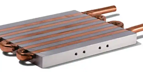
Custom Liquid Cooling Plates provide a dedicated heat-transfer path for power electronics inside motor controllers. During repeated acceleration, high-current operation, or extended workloads, switching devices generate heat that must be removed without increasing the controller's overall size.
The challenge is to create a plate that matches the power module arrangement, maintains effective contact with heat-generating components, and distributes coolant through the available space. Channel geometry, mounting strength, and sealing details must be considered together because changes in one area can affect the entire assembly.
2. Four Requirements That Shape the Design
● Power module heat removal: We examine module locations, contact areas, expected heat loads, and coolant flow requirements before finalizing the channel layout. This helps direct coolant toward critical thermal zones.
● Space-efficient construction: When the controller has limited installation space, channels, mounting holes, and coolant ports must fit within a carefully defined envelope. Integrated features can simplify assembly and reduce unnecessary external connections.
● Mechanical stability under vibration: Motor controllers may operate in vehicles or equipment exposed to repeated vibration. We review fastening locations, plate thickness, port support, and local material removal to avoid creating unnecessarily weak sections.
● Reliable coolant sealing: Seal grooves, mating surfaces, and port interfaces require appropriate dimensions and surface quality. The sealing arrangement must match the selected gasket, O-ring, or joining method.
3. How We Machine Custom Liquid Cooling Plates
Our manufacturing approach starts with the component's function and drawing requirements rather than applying one channel pattern to every project.
1. Review the CAD model: Identify thermal contact areas, coolant connections, mounting interfaces, minimum wall thickness, and critical tolerances.
2. Prepare the material: Confirm the specified alloy and stock dimensions. Establish machining datums that keep channel features and external interfaces aligned.
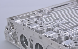
3. Machine the cooling structure: Use CNC milling and suitable cutting tools to produce the required passages, ports, mounting holes, and sealing features. Tool access and chip evacuation must be considered, particularly for deep or narrow channels.
4. Finish and clean: Remove accessible burrs, clean passages, and inspect surfaces that contact power modules or sealing elements. Residual chips and machining debris must not obstruct coolant flow.
5. Verify the finished part: Check drawing-critical dimensions, hole positions, and contact-surface flatness. Perform the agreed pressure or leak test when specified. Thermal testing may be needed to validate performance under representative operating conditions.
The manufacturing route depends on whether the design uses a single machined body, a covered channel structure, or joined plate sections. Joining operations introduce additional requirements for alignment, distortion control, and leak verification.
For project-specific manufacturing support, visit Start Precision and review its precision machining capabilities.
4. Key Features and Inspection Priorities
| Design feature | Manufacturing focus | Verification |
| Internal passages | Channel dimensions and tool access | Geometry and cleanliness |
| Module interface | Flatness and surface finish | Contact-surface inspection |
| Mounting points | Hole positions and thread quality | Assembly fit |
| Seal interfaces | Groove dimensions and surface condition | Seal fit and leak testing |
| Coolant ports | Thread and connection specifications | Connection integrity |
Material selection should account for thermal conductivity, mass, corrosion compatibility, and the operating environment. Aluminum alloys are commonly considered when low weight and efficient heat transfer are priorities, but the final choice depends on the complete cooling system.
5. Example: Redesigning a Crowded Controller Cooling Assembly
Consider a motor controller whose power modules and coolant connections compete for limited enclosure space. A generic plate may force awkward pipe routing or leave some module locations poorly matched to the available cooling passages.
A project-specific redesign could reposition the channels around the module footprint, relocate ports to suit the enclosure, and incorporate mounting features directly into the plate. The engineering review would also examine material thickness near threaded ports and sealing surfaces to preserve structural support.
After machining, dimensional inspection and leak testing would verify manufacturing conformity. A separate thermal evaluation under representative load would establish whether the revised arrangement delivers the required cooling performance. These are proposed engineering steps, not claimed results from a completed customer project.
6. Conclusion
A dependable motor-controller cooling plate combines a suitable flow path with precise interfaces, robust mounting features, and verified sealing. Reviewing these requirements before machining helps reduce avoidable design changes and assembly problems.
Start Precision supports custom precision-machining projects according to customer drawings and agreed inspection requirements. Contact us to discuss your manufacturing needs and evaluate a suitable production route for your liquid cooling plate.
Frequently Asked Questions
1. What information is needed to manufacture a custom cooling plate?
Provide a 2D drawing or 3D CAD model, material specification, order quantity, critical tolerances, coolant details, sealing requirements, and applicable test criteria.
2. Can CNC machining produce complex cooling channels?
CNC milling can produce many channel geometries. Feasibility depends on passage dimensions, depth, tool access, internal corner requirements, and the chosen plate construction.
3. How is sealing reliability checked?
Inspection may include groove measurements, mating-surface checks, joining-process verification, and a specified pressure or leak test. The procedure should reflect the actual service requirements.
4. Does a leak test prove cooling performance?
No. Leak testing evaluates containment under defined test conditions. Thermal performance requires separate evaluation based on heat load, coolant flow, temperature, and system configuration.
Add: Building 3No.277 Zhen'an Middle Road, Chang'an Town,Dongguan,Guangdong, China
Tel:+86-769-82855591
Copyright © 2019 All Rights Reserved Dongguan Start Precision Technology Co., Ltd. Tel: +86-769-82855591
Add: No. 277 Zhen'an Middle Road, Chang'an Town, Dongguan, Guangdong, China



 中文版
 English