Liquid Cooling Plate Machining for Thin-Wall Profiles
Date:2026-10-27Article editor:Starting Point PrecisionViews:481. Machining Challenges of Thin-Wall Cooling Plates
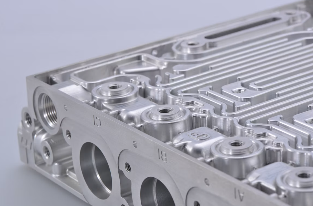
Liquid Cooling Plate Machining becomes particularly demanding when a component contains thin ribs, deep flow channels, and broad thermal contact surfaces. Removing material from these areas changes the plate's structural stiffness, making dimensional stability a key manufacturing concern.
For custom liquid cooling plates, even minor deformation may affect assembly alignment, thermal contact, or sealing performance. A reliable machining strategy must therefore coordinate fixture design, tool engagement, material stress management, and inspection throughout production.
2. How We Machine Thin-Wall Profiles
2.1 Develop a Geometry-Based Machining Plan
Before machining begins, we review the supplied drawings and 3D models to identify fragile sections, critical sealing areas, channel intersections, and mounting interfaces.
The machining sequence is planned around the component's changing rigidity. Where the design allows, additional material is retained during roughing to support thin sections until the main geometry has been established.
2.2 Apply Controlled Workholding
A thin-wall cooling plate can flex if the fixture applies force at unsuitable locations. Our process planning considers how the workpiece is supported before, during, and after cutting.
● Position support points near areas exposed to machining forces.
● Distribute clamping pressure rather than concentrating it on narrow walls.
● Evaluate dedicated fixtures or vacuum workholding when suitable for the component.
● Check dimensional changes after unclamping to identify fixture-induced deformation.
This approach aims to maintain a stable machining position without relying on excessive clamping force.
2.3 Reduce Cutting-Induced Deformation
Long, slender ribs and narrow channels are sensitive to tool pressure and vibration. We select cutters, toolpaths, feed rates, and cutting depths according to the alloy and feature geometry.
● Rough out major cavities in controlled stages.
● Avoid removing excessive material from one side while the opposite side remains highly stressed.
● Use lighter finishing passes on critical walls and contact surfaces.
● Review tool wear and vibration when surface quality or dimensions become inconsistent.
The objective is to remove material predictably while preserving the remaining structure.
2.4 Manage Material Stress
Machining can release residual stress already present in the stock. As material is removed, the plate may gradually change shape, particularly when large cavities leave an uneven distribution of material.
Depending on the alloy and material condition, we may consider stress-relieved stock, intermediate stabilization, or a roughing stage followed by a separate finishing operation. Any additional treatment must be compatible with the material specification and the customer's requirements.
2.5 Inspect Flatness After Machining
A plate that appears flat while clamped may distort after removal from the fixture. For this reason, inspection should reflect the specified measurement condition.
Depending on the drawing tolerance, suitable methods may include a surface plate and indicator, precision dimensional instruments, or coordinate measuring equipment.
Critical inspection points include:
● Overall plate flatness and thickness.
● Thin-wall thickness and channel dimensions.
● Sealing-face geometry and surface finish.
● Port positions, mounting holes, and assembly interfaces.
3. Thin-Wall Machining Control Plan
| Process stage | Main control | Quality objective |
| Drawing review | Identify flexible regions and critical dimensions | Establish machining priorities |
| Fixture preparation | Match support to part geometry | Limit clamping deformation |
| Rough milling | Stage material removal and monitor cutting forces | Preserve structural stability |
| Stress management | Select suitable material condition and process sequence | Reduce distortion risk |
| Finish machining | Refine walls and contact surfaces | Meet dimensional requirements |
| Final inspection | Measure the released component | Verify flatness and feature accuracy |
4. Custom Cooling Plate Manufacturing Support
Thin-wall cooling plates may be required for power electronics, battery thermal management, laser equipment, and other compact thermal systems. Each application presents different requirements for weight, flow-channel geometry, sealing, and surface contact.
Start Precision supports custom manufacturing discussions based on customer drawings, 3D models, material specifications, and inspection requirements. Visit the Start Precision homepage or review our precision machining capabilities to learn more.
For background on lightweight-alloy machining and material behavior, consult the technical literature available through Materials.
Contact us to discuss your manufacturing needs. Share your cooling plate design, material, minimum wall thickness, and flatness tolerances so the manufacturing approach can be evaluated for your project.
Frequently Asked Questions
1. What causes deformation in thin-wall cooling plates?
Common causes include excessive clamping force, cutting pressure, vibration, uneven material removal, and residual stress released during machining.
A suitable fixture, staged roughing, controlled finishing cuts, and measurements after unclamping help identify and reduce deformation.
No. Its suitability depends on the alloy, stock condition, geometry, and dimensional requirements. The process should be selected for the specific component rather than applied automatically.
Provide the 2D drawing or 3D model, material specification, wall thickness, channel layout, quantity, required tolerances, and any leak-testing or inspection requirements.
Add: Building 3No.277 Zhen'an Middle Road, Chang'an Town,Dongguan,Guangdong, China
Tel:+86-769-82855591
Copyright © 2019 All Rights Reserved Dongguan Start Precision Technology Co., Ltd. Tel: +86-769-82855591
Add: No. 277 Zhen'an Middle Road, Chang'an Town, Dongguan, Guangdong, China



 中文版
 English