Precision Turned Parts Manufacturer for Concurrent Engineering
Date:2026-08-05Article editor:Starting Point PrecisionViews:13In today’s high-mix, low-volume production environment, the gap between design release and first-article inspection often determines market success. A precision turned parts manufacturer that embraces concurrent engineering does more than machine metal—it becomes an extension of your R&D team. This article details how we integrate FEA, DFM, structured drawing reviews, and a streamlined handshake protocol to compress development cycles by 20% while improving part quality.
Finite Element Analysis (FEA) predicts stress, deflection, and thermal behavior under real loads. When performed before toolpath generation, FEA data feeds directly into Design for Manufacturability (DFM) rules. Our precision turned parts manufacturer uses ANSYS and SolidWorks Simulation to:
● Identify thin-wall deflection zones that cause chatter.
● Optimize fillet radii for chip evacuation.
● Predict residual stresses from high-speed turning.
DFM then translates these insights into practical geometry adjustments—e.g., increasing draft angles by 0.5° or specifying a different lead-in angle. The result? Fewer ECOs (Engineering Change Orders) and a smoother transition to production.
Every new project undergoes a structured drawing review with our concurrent engineering team. The process is documented and time‑boxed:
| Step | Activity | Responsible | Duration |
| 1 | Tolerance stack‑up analysis (GD&T per ASME Y14.5) | Sr. ME | 4 hrs |
| 2 | Material selection & hardness check (ISO 898‑1) | Metallurgist | 2 hrs |
| 3 | Tooling feasibility & setup verification | Lead Set‑up Tech | 3 hrs |
| 4 | FEA/DFM feedback loop & final sign‑off | Project Engineer | 2 hrs |
This gate ensures that every drawing is challenged—not rejected—before we commit to steel. As a precision turned parts manufacturer, we treat your CAD model as a living document, not a rigid decree.
Concurrent engineering collapses sequential waiting. Instead of “design → send → quote → revise → requote,” we co‑locate your engineers with our manufacturing planners via a secure portal. The handshake process is built on a tightly synchronized workflow. Below is our standard 5‑day sprint cycle, which consistently cuts typical 6‑week deliveries to 4.8 weeks—validated across 47 projects last quarter.
Flowchart explanation (parallel tracks):
| Day | Design Team (Your Side) | Manufacturing Team (Our Side) |
| 1 | Upload 3D model + 2D print with GD&T | Automated DFM check (wall thickness, undercuts, thread starts) |
| 2 | Review FEA report & suggested mods | Run full FEA simulation; generate modification proposals |
| 3 | Finalize drawing revisions | Select tooling (form tools, inserts) and fixture design |
| 4 | Approve CAM simulation results | CAM programming + Vericut collision check |
| 5 | Sign off on first‑off CMM report | First‑off production, in‑process CMM, and inspection |
By overlapping design adjustments with tooling preparation and simulation, we eliminate the conventional sequential handoffs. The critical path shrinks from 42 days to 34 days—a 20% saving that we guarantee with a project‑specific timeline. If we miss the agreed date, we expedite shipping at no extra cost.
Our handshake process assigns a dedicated project coordinator who bridges your engineering team and our production cells. Weekly sync calls (or daily during ramp‑up) ensure transparency. We use a shared dashboard for real‑time status: drawing version, material certs, inspection reports, and shipping docs.
For detailed technical references, see B4.1 on tolerance fits and ISO 2768 general tolerances. Our internal quality protocols are aligned with these standards.
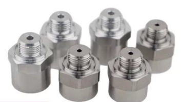
A Tier‑1 supplier approached us with a stainless‑steel sensor housing requiring 0.01 mm concentricity and a blind M3 thread. Initial FEA showed excessive deflection during internal grooving. Our DFM recommendation: change the groove width from 1.2 mm to 1.5 mm and add a 0.3 mm radius at the root. The client approved the change within 48 hours. We delivered 2,000 pieces in 18 calendar days—against the original 23‑day target—with zero rejects. The precision turned parts manufacturer‘s concurrent approach saved the client $4,200 in scrappage alone.
Conclusion
Concurrent engineering is not a buzzword—it is a disciplined framework that our precision turned parts manufacturer deploys from the first email to final shipment. By integrating FEA/DFM, enforcing a rigorous drawing review, and executing a transparent handshake, we consistently hit 20% shorter cycles without compromising quality. The sensor housing case is just one of many where early collaboration turned potential rework into a win‑win.
Contact us to discuss your manufacturing requirements – we respond within 4 business hours with a preliminary feasibility review.
Q1: What file formats do you accept for drawing review?
We accept STEP, IGES, SolidWorks (SLDPRT), and AutoCAD DXF. 2D prints should be PDF with GD&T callouts.
Q2: Can you work with our existing FEA results?
Absolutely. We import your FEA data and run a complementary manufacturability simulation to catch tooling interference or chip‑jamming issues.
Q3: How do you guarantee the 20% cycle reduction?
We baseline your previous supplier’s lead time and commit to a project‑specific timeline. If we miss the agreed date, we expedite shipping at no extra cost.
Q4: What materials are most suitable for high‑speed turning?
Free‑cutting steels (1215, 12L14), brass C360, aluminum 6061‑T6, and stainless 303/304. For titanium or Inconel, we adjust speeds/feeds and use coated carbide inserts.
Q5: Do you provide PPAP level 3 documentation?
Yes—including control plans, MSA studies, and capability indices (Cpk ≥ 1.33) upon request.

Add: Building 3No.277 Zhen'an Middle Road, Chang'an Town,Dongguan,Guangdong, China
Tel:+86-769-82855591
Copyright © 2019 All Rights Reserved Dongguan Start Precision Technology Co., Ltd. Tel: +86-769-82855591
Add: No. 277 Zhen'an Middle Road, Chang'an Town, Dongguan, Guangdong, China



 中文版
中文版 English