CNC Milling Parts Machining: Essential DFM Best Practices to Reduce Costs & Lead Times
Date:2026-05-28Article editor:Starting Point PrecisionViews:482Design for Manufacturability (DFM) is the cornerstone of cost‑effective CNC milling parts machining. By applying proven DFM best practices, engineers can avoid common issues like excessive tool wear, long cycle times, and scrapped parts. Below are the most critical guidelines to optimize your milled components.
End mills are cylindrical, so internal corners will always have a radius. A sharp 90° corner requires EDM or hand finishing, increasing cost. Recommendation: Use a corner radius equal to or slightly larger than the tool diameter (e.g., Ø6 mm end mill → R3 mm).
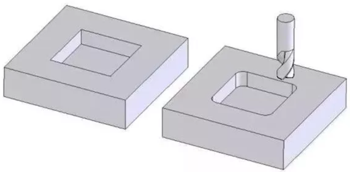
Comparison of sharp vs. radiused internal corners in CNC milling
Deep cavities challenge tool rigidity and chip evacuation. Keep cavity depth ≤ 4× tool diameter for standard tools. For deeper features, specify specialized tooling or step‑down strategies. This reduces vibration and improves surface finish.
Design features so that standard‑length end mills can reach all surfaces. Avoid deep, narrow slots where the tool holder would collide with the workpiece. Best practice: Add relief grooves or split the design into multiple set‑ups if necessary.
Learn more about Guide to CNC Milling Tool Selection.
Tighter tolerances (±0.005 mm) exponentially increase machining time and inspection cost. Only assign critical dimensions where functional. For most features, ±0.125 mm is economical. Tip: Use GD&T callouts to communicate which surfaces are truly critical.
Thin walls (≤0.8 mm for metals) deflect during milling, causing chatter and poor accuracy. Maintain wall thickness ≥1.5 mm for aluminum and ≥2 mm for steel. Similarly, thin floors can vibrate; add ribs or increase thickness where possible.
Hole diameters, slot widths, and radii should match common end mill sizes (e.g., 3, 4, 6, 8, 10, 12 mm). Custom‑ground tools increase lead time and cost. Check: ISO Standard End Mill Dimensions– Use this reference to align your design with off‑the‑shelf tools.
Each new workpiece orientation adds non‑cutting time and tolerance stack‑up. Design parts to be machined in as few set‑ups as possible – preferably one or two. Use features like locating holes or flat reference surfaces to enable quick fixturing.
Sharp edges are dangerous and prone to burrs. Specify a 0.2–0.5 mm chamfer or radius on all external edges. This simple DFM step reduces deburring time and improves handling safety.
| Feature | Recommended Practice |
|---|---|
| Internal corners | Radius ≥ tool diameter × 0.5 |
| Depth/Diameter | ≤4:1 for standard tools |
| Wall thickness | ≥1.5 mm (aluminum) |
| Tolerances | ±0.125 mm unless critical |
By applying these CNC milling DFM best practices, you will achieve faster quotes, lower unit costs, and higher quality parts. Always consult with your machining partner early in the design phase.
1. What is the most common DFM mistake in CNC milling?
Specifying unnecessary tight tolerances on every dimension, which triples machining time without functional benefit.
2. How does corner radius affect tool life?
A sharp internal corner forces a tiny tool diameter or EDM, both slow. A generous radius allows larger, more rigid end mills and extends tool life significantly.
3. Can I machine undercuts with standard CNC milling?
Yes, but undercuts require T‑slot cutters or lollipop tools, increasing setup complexity. Redesign to avoid them unless absolutely necessary.
Add: Building 3No.277 Zhen'an Middle Road, Chang'an Town,Dongguan,Guangdong, China
Tel:+86-769-82855591
Copyright © 2019 All Rights Reserved Dongguan Start Precision Technology Co., Ltd. Tel: +86-769-82855591
Add: No. 277 Zhen'an Middle Road, Chang'an Town, Dongguan, Guangdong, China



 中文版
中文版 English