
How 5‑Axis Integrated Machining Performs CNC Turning of Precision Parts
Date:2026-05-21Article editor:Starting Point PrecisionViews:267While many shops know the benefits of 5‑axis technology, fewer understand the exact workflow behind 5‑axis integrated machining – where turning, milling, drilling, and contouring happen in one setup. This article focuses on the “how”: from programming to final cut, explaining each step for producing CNC turning precision parts with 5‑axis integration.
Step 1: Selecting a True 5‑Axis Turn‑Mill Center
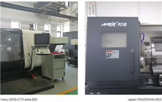
Not every lathe with live tooling is a 5‑axis machine. You need a mill‑turn center with a B‑axis tilting spindle (usually ±120°) and a C‑axis rotary on the main or subspindle. Examples include DMG MORI NTX series or Mazak Integrex. These machines allow simultaneous control of X, Y, Z, B, and C axes.


5‑axis mill‑turn machine with B‑axis tilting head (illustrative)
Standard CAM software (like Mastercam Mill‑Turn, Hypermill, or ESPRIT) is required. The programmer:
◆ Defines the part’s coordinate system – usually at the main spindle face.
◆ Creates turning operations (rough/finish) along the C‑axis rotation.
◆ For non‑cylindrical features, activates simultaneous 5‑axis toolpaths: the B‑axis tilts the tool while the C‑axis rotates the part, keeping the tool normal to the surface.
◆ Uses collision checking to avoid holder‑to‑part contact during tilt.
Mainstream CAM Programming Software Application Comparison Table
| Application Scenario | Recommended Software | Core Advantages |
|---|---|---|
| Beginner, 2D/3-axis, small & medium factories | Mastercam | Easy to learn, complete post-processors, universal for part machining |
| Mold, high-speed machining, electrode processing | PowerMill, Cimatron | Smooth toolpath, clean corner finishing, professional for mold industry |
| 5-axis linkage, aerospace parts, impeller & blade | Hypermill, NX(UG) | Powerful multi-axis strategies, accurate collision avoidance, excellent for complex surfaces |
| Programming matched with SolidWorks modeling | SolidCAM | Seamless integration with SW, automatic update after model modification, ideal for mill-turn machining |
The goal is to machine the complete part without re‑clamping. Typical strategies:
◆ Main spindle chuck + tailstock for long turned shafts.
◆ Subspindle pick‑off for second‑side operations – the part is transferred automatically.
◆ Steady rests for thin‑wall tubes when the B‑axis mills laterally.
One critical “how‑to”: always program a synchronized transfer with the subspindle before any 5‑axis milling on the back face.
Here’s a typical sequence for a precision part like a valve body with angled holes and eccentric cam:
1. Rough turn OD/ID – using C‑axis positioning.
2. Simultaneous 5‑axis roughing of a complex contour – e.g., a helical cam groove – where the B‑axis tilts 15° while the C‑axis rotates continuously, and Z feeds linearly.
3. Finish turning of cylindrical surfaces – same setup, just use turning tools with C‑axis lock at 0°.
4. Drill angled cross holes – B‑axis tilts to required angle, C rotates part to hole position, then live tool drills.
5. Mill a freeform pocket on the face – simultaneous B‑ and C‑motion keeps the ball endmill tangent to the pocket walls.
All without removing the part from the machine. This eliminates tolerance stack‑up from multiple fixturings.
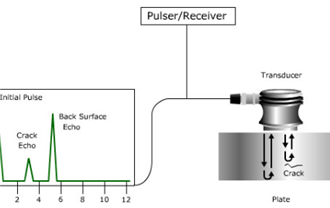
To guarantee precision, a 5‑axis integrated machine uses a touch probe mounted in the turret or spindle. The probe:
◆ Measures part zero after gripping.
◆ Checks critical diameters and adjusts tool offsets automatically.
◆ Verifies B‑axis orientation before deep angled holes.
This feedback loop turns the machine into a closed‑loop manufacturing cell.
◆ Challenge 1: Tool interference when B is at extreme angles.
Solution 1: Use slim‑profile holders and simulate with machine‑specific 3D models.
◆ Challenge 2: Long cycle time due to unnecessary simultaneous moves.
Solution 2: Use 3+2 indexing for flat features, only full 5‑axis for freeform surfaces.
◆ Challenge 3: Poor surface finish on turned parts after milling.
Solution 3: Separate turning finishing from milling – finish turn first, then mill, or use a “finish turning” pass after milling if material permits.
Q1. How does simultaneous 5‑axis differ from 3+2 machining for turned parts?
In 3+2 (positional), the B and C axes lock at an angle, then turning/milling occurs. In simultaneous 5‑axis, all axes move continuously while the tool is cutting – essential for undercuts, turbine blades, or cam lobes where the contact point moves across a curved surface.
Q2. Can I use standard turning inserts for 5‑axis mill‑turn?
Yes for pure turning. But for simultaneous 5‑axis milling, you need ball nose or toroidal endmills. Some operations combine turning and milling in one toolpath – then use a “mill‑turn” dedicated insert (e.g., from Horn or Walter).
Use a CAM operation called “C‑axis contour” for eccentric turning – the C‑axis rotates the workpiece offset from center while X interpolates. For 5‑axis, combine B tilt with C rotation to keep the drill axis aligned with the angled hole vector.
First‑time setup can take 2–4 hours (tool assembly, CAM post verification). However, subsequent runs are under 30 minutes because no re‑fixturing. For high‑mix low‑volume, this saves days of lead time.
Simulate collision in CAM with the exact tailstock/quill model. Alternatively, program a tool change to a shorter holder or use a subspindle without tailstock for short parts.
A spinal screw requires turned threads, a milled hexalobular socket in the head, and an angled through‑hole for bone cement. Using 5‑axis integrated machining:
◆ Turn thread and OD – C‑axis.
◆ Tilt B to 15°, rotate C to hole position – drill angled hole.
◆ B back to 0°, mill hex socket with a live tool.
◆ All in < 3 minutes per part, with ±0.005 mm accuracy.
For deeper technical specs, visit Modern Machine Shop guide on 5‑axis for turned parts.
Mastering how to do 5‑axis integrated machining for CNC turning precision parts requires the right machine, CAM software, and a step‑by‑step approach: setup, probing, simultaneous toolpaths, and collision avoidance. Once learned, it delivers unmatched complexity and accuracy in one operation.

Add: Building 3No.277 Zhen'an Middle Road, Chang'an Town,Dongguan,Guangdong, China
Tel:+86-769-82855591
Copyright © 2019 All Rights Reserved Dongguan Start Precision Technology Co., Ltd. Tel: +86-769-82855591
Add: No. 277 Zhen'an Middle Road, Chang'an Town, Dongguan, Guangdong, China
 中文版
中文版 English