Mastering Aluminum CNC Turning Parts in Thin-Wall Applications
Date:2026-08-15Article editor:Starting Point PrecisionViews:197Thin-wall aluminum components are ubiquitous in aerospace, automotive, and electronics—yet they remain one of the most challenging jobs for any machinist. The combination of aluminum’s low stiffness and high thermal expansion demands a disciplined approach to fixturing, cutting parameters, and inspection. This article distills proven tactics for producing high-quality Aluminum CNC Turning Parts with wall thicknesses under 1.5 mm, focusing on four critical pillars: clamping strategy, heat management, roundness verification, and real-world problem solving.
Unlike rigid steel workpieces, thin-wall aluminum tubes and shells distort elastically under even moderate chuck pressure. The goal is to apply just enough gripping force to transmit torque without ovalizing the part.
| Clamping Method | Typical Application | Risk Level | Recommended Pressure Range |
| 3‑Jaw Hard Chuck | Roughing, heavy cuts | High (point loads) | 2–4 bar (soft jaws) |
| Collet Chuck (5C/16C) | Finishing, uniform OD | Moderate | 1.5–3 bar |
| Piezo‑Controlled Actuator | Ultra‑thin walls (<0.8 mm) | Low (adaptive) | 0.5–1.5 bar |
| Expanding Mandrel (ID grip) | Hollow cylinders | Very Low | <1 bar (air‑assisted) |
Practical rules:
● Use soft (aluminum or copper) jaws machined to the part’s O.D. to spread contact.
● Reduce clamping force by 40–50% for finishing passes compared to roughing.
● For ID gripping, employ hydraulic expansion arbors that self‑center and minimise radial stress.
● Always perform a “squeeze test” – measure the part’s free‑state diameter before and after clamping; accept only ≤0.01 mm deflection.
For advanced fixturing solutions, explore the clamping systems referenced in SME’s precision machining guide.
Aluminum’s thermal conductivity (≈205 W/m·K) is high, but thin walls have low thermal mass. Heat quickly accumulates, causing:
● Thermal expansion during cutting → undersized OD after cooling.
● Residual tensile stress on the surface → warpage after unclamping.
Mitigation toolkit:
● High‑pressure coolant (≥70 bar) directed at the cutting edge – reduces temperature by up to 150°C.
● Polycrystalline diamond (PCD) inserts – their low coefficient of friction minimises frictional heat.
● Peck turning – intermittent cuts allow the wall to cool between passes.
● Feed rate >0.15 mm/rev – thicker chips carry away more heat (contrary to intuition).
● Stress‑relief annealing (150°C for 2 hours) between rough and finish operations, if batch size justifies it.
A useful reference for cutting data optimisation is the Machining Doctor’s aluminum turning calculator, which adjusts speeds and feeds based on wall rigidity.
Standard two‑point micrometers often mask trilobular (3‑lobe) out‑of‑roundness caused by uneven clamping or tool pressure. For Aluminum CNC Turning Parts in thin‑wall applications, use:
● Air gauging – non‑contact, measures average diameter and roundness in <2 seconds.
● Coordinate Measuring Machine (CMM) with a low‑force probe (<0.1 N) – captures 8–12 points per cross‑section.
● Laser scanning – for high‑volume production, in‑line scanning at 1000 Hz detects distortion in real time.
Acceptance criteria (per ISO 1101):
● For walls 0.8–1.2 mm: roundness ≤ 0.01 mm.
● For walls <0.8 mm: roundness ≤ 0.01 mm (the highest precision is capped at 0.01 mm).
Always measure at three axial positions (near chuck, mid‑span, and free end) because deflection varies along the length.
Background: A medical device manufacturer needed 6061‑T6 aluminum sleeves, 65 mm O.D. × 62 mm I.D. (wall = 1.5 mm), length 80 mm, with a roundness tolerance of 0.01 mm and surface finish Ra 0.8 µm.
Initial problem: First batch had 35% rejection – ovality up to 0.035 mm and chatter marks at the free end.
Our intervention (Start Precision team):
● Replaced 3‑jaw chuck with a piezo‑controlled collet (clamping force reduced from 4 bar to 1.2 bar).
● Switched from uncoated carbide to PCD inserts with a 0.2 mm nose radius.
● Applied MQL (minimum quantity lubrication) with 80 bar through‑tool coolant.
● Added a tailstock live center with adjustable pressure to support the free end.
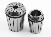
Results:
● Roundness improved to 0.009–0.01 mm (100% within the 0.01 mm tolerance).
● Cycle time increased by only 8% due to higher permissible cutting speed (from 300 to 450 m/min).
● Rejection rate dropped to 2.1%.
This case underscores that systematic adjustments in fixturing and thermal control directly transform scrap into profit.
Producing reliable Aluminum CNC Turning Parts in thin‑wall geometries is not a matter of luck—it is a matter of disciplined engineering. Master the triad of controlled clamping, heat evacuation, and precision roundness inspection, and your scrap rate will plummet. Remember that every thin‑wall job is unique; always validate your process with a sacrificial test piece.
For a deeper dive into custom fixturing and process optimisation, visit Start Precision’s CNC turning services – where we turn challenging blueprints into repeatable successes.
If you are facing thin‑wall aluminum turning difficulties or planning a new production run, we invite you to contact us to discuss your manufacturing needs. Our engineers are ready to analyse your drawings and propose a risk‑free pilot program.
Q1: What is the minimum wall thickness that can be CNC turned in aluminum?
A: With advanced clamping (e.g., expanding mandrels) and PCD tools, walls as thin as 0.4 mm are achievable, though tolerances become very tight. For economical production, 0.8–1.2 mm is recommended.
Q2: How do I know if my clamping force is too high?
A: Measure the part’s O.D. while clamped and after release. If the difference exceeds 0.01 mm for a 50 mm diameter, reduce the chuck pressure and use soft jaws.
Q3: Does coolant type matter for thin‑wall aluminum?
A: Yes. Use a semi‑synthetic emulsion with extreme‑pressure (EP) additives at 6–8% concentration. Avoid neat oils as they reduce heat transfer. High‑pressure through‑tool coolant is strongly preferred.
Q4: Can I turn thin‑wall aluminum without a tailstock?
A: For L/D ratios > 2.5, a tailstock (or steady rest) is essential to prevent deflection at the free end. For shorter parts, it may be optional if you use a short overhang and reduced feed.
Q5: How often should I recalibrate roundness measuring equipment?
A: Air gauges and CMM probes should be calibrated daily with a master ring. Additionally, perform a GR&R study every 6 months to ensure repeatability under shop conditions.

Add: Building 3No.277 Zhen'an Middle Road, Chang'an Town,Dongguan,Guangdong, China
Tel:+86-769-82855591
Copyright © 2019 All Rights Reserved Dongguan Start Precision Technology Co., Ltd. Tel: +86-769-82855591
Add: No. 277 Zhen'an Middle Road, Chang'an Town, Dongguan, Guangdong, China



 中文版
中文版 English