
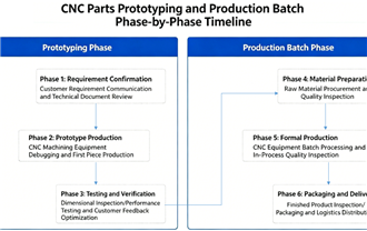
Custom Part Machining: From Drawing to Finished Product
Date:2026-05-05Article editor:Starting Point PrecisionViews:18Transforming a concept into a precision component depends on a tightly controlled custom part machining workflow. For engineers and buyers, understanding each stage—from the initial drawing to the final delivered part—is the key to consistent quality, cost control, and on-time delivery. This guide walks through the entire custom part machining process while connecting you to the essential design standards, material data, and inspection resources that support reliable production.
Step 1: Technical Drawing and CAD Modeling
Every custom part machining project begins with a fully defined digital blueprint. A 3D model is created in software such as SolidWorks or Fusion 360, then detailed 2D drawings are extracted with dimensions, tolerances, and surface finish callouts. Applying geometric dimensioning and tolerancing (GD&T) at this stage removes ambiguity and directly reduces machining rework.
Before toolpaths are generated, the design should undergo a manufacturability check.
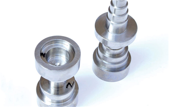
Design for Manufacturability (DFM) Review — our engineers validate the drawing to prevent costly delays in custom part machining.The visual relationship between a CAD model and the finished metal component is immediately clear in this side‑by‑side.

CAD Model vs. Finished Custom Machined Part
Step 2: CAM Programming – Turning the Drawing into Toolpaths
The approved 3D model is imported into computer‑aided manufacturing (CAM) software. Here, a programmer builds the toolpath strategy that drives custom part machining equipment. Decisions on cutting speed, stepover, and tool selection directly influence surface finish, dimensional stability, and cycle time. An optimized CAM program also reduces tool wear and keeps project costs down.
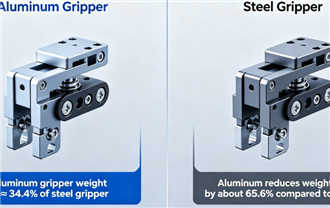
Selecting the right material is a critical decision point in any custom part machining job. Common choices include aluminum alloys (6061, 7075), stainless steels (304, 316L), engineering plastics (PEEK, Delrin), and brass. The selection balances mechanical strength, machinability, corrosion resistance, and budget.Raw stock is then cut to size, verified for composition, and fixtured onto the machine bed to begin the first metal‑cutting operation.Learn more about MatWeb Material Property Database — an independent source for comparing tensile strength, hardness, and thermal characteristics.
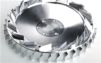
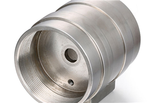
This is the core execution phase of custom part machining. Depending on the part geometry, production involves CNC milling, turning, or combined mill‑turn operations. Multi‑axis machines produce intricate angles and undercuts while maintaining tight tolerances, and in‑process probing systems measure critical features in real time to validate the drawing’s requirements.
Throughout machining, high‑pressure coolant and controlled chip evacuation maintain thermal stability, which is essential for holding close dimensions.
After machining, parts often receive surface treatments such as anodizing, bead blasting, powder coating, or passivation to enhance performance and appearance. The final step in the custom part machining process is a comprehensive quality inspection using coordinate measuring machines (CMMs), optical comparators, and roughness testers. Every dimension on the drawing is verified, and a full inspection report is generated.
The approved product is then carefully packaged, accompanied by material certifications, and shipped.
By following a structured path from drawing through programming, precision machining, and verified quality, the finished product accurately reflects the original design intent. A reliable custom part machining process gives you parts that not only fit but perform exactly as required.
Frequently Asked Questions
Q1:What drawing formats are required for custom part machining?
STEP (.stp) and IGES (.igs) are the preferred neutral 3D formats. For 2D drawings, a PDF with detailed dimensions and tolerances works best. Native CAD files like SolidWorks (.sldprt) can often be used after version checks.
Q2:How long does the custom part machining process take from drawing to shipping?
Timelines depend on complexity. A straightforward turned part can ship in 3–5 business days, while a complex 5‑axis milled part with anodizing typically takes 2–3 weeks. A detailed lead time is always provided after the drawing review.
Q3:How do you ensure the finished part exactly corresponds to the drawing?
Through in‑process probing, first‑article inspection, and a final CMM layout against the 2D drawing. Dimensional inspection reports are available for full traceability, confirming that every characteristic is within specification.
Q4:Can custom part machining work from a physical sample instead of a drawing?
Yes. Reverse engineering services use 3D scanning to create a CAD model and drawing from a physical sample. A detailed hand sketch with dimensions can also be converted into a professional digital drawing before machining begins.

Add: Building 3No.277 Zhen'an Middle Road, Chang'an Town,Dongguan,Guangdong, China
Tel:+86-769-82855591
Copyright © 2019 All Rights Reserved Dongguan Start Precision Technology Co., Ltd. Tel: +86-769-82855591
Add: No. 277 Zhen'an Middle Road, Chang'an Town, Dongguan, Guangdong, China
 中文版
中文版 English